
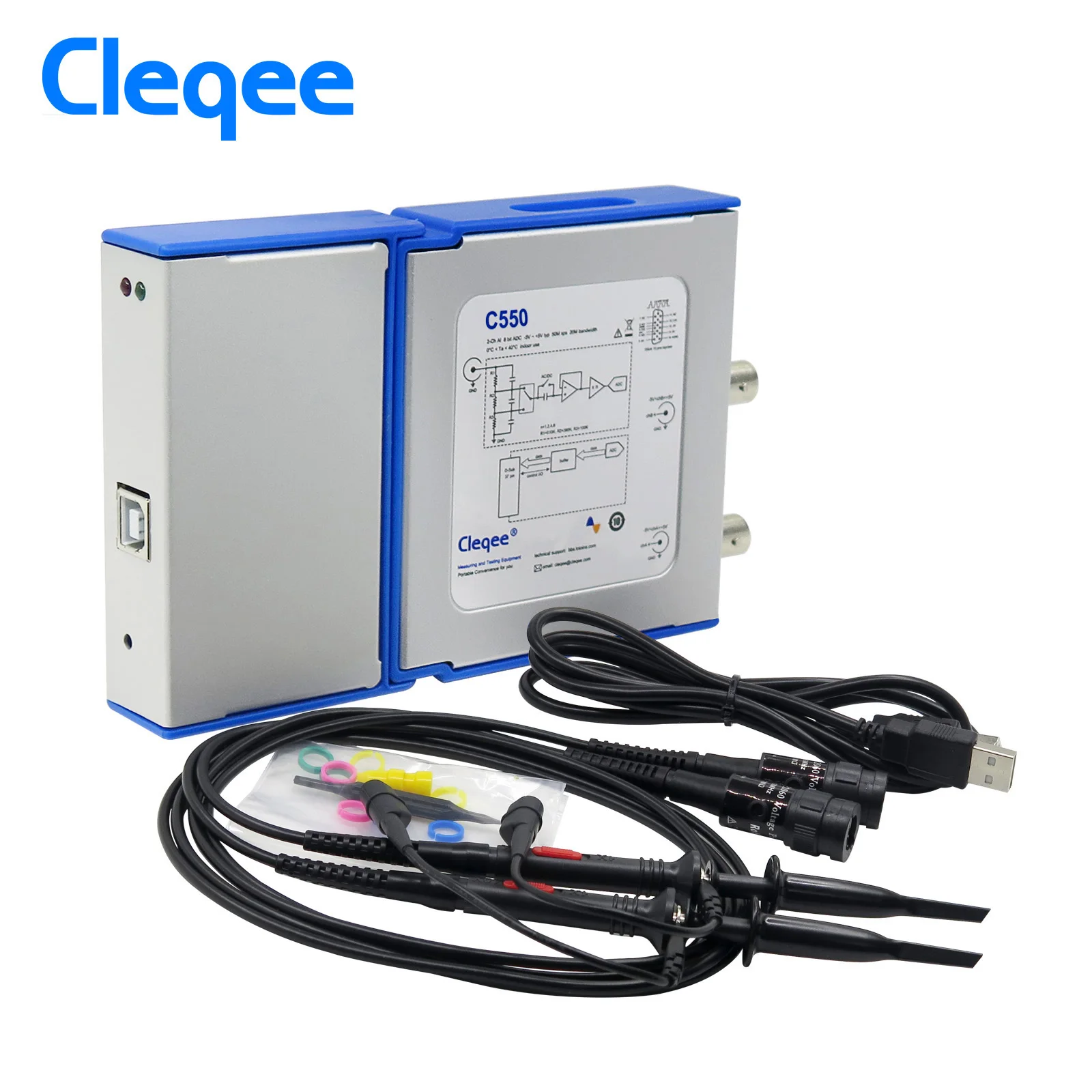

Cleqee C550 PC Virtual Digital Handheld Oscilloscope 2 Channel Bandwidth 50Mhz sampling data 1G with probe USB cable
- Category: Oscilloscopes >>>
- Supplier: Changzhou Leqi Electronic Technology Ltd.
Share on (62056336940):
Product Overview
Description
C550 Software download:
https://www.dropbox.com/sh/z2u1oqicff5e2zs/AACc2mQuteRbmqH8QyuPMyRBa?dl=0
C550 specifications
Model | C550 | |
Connector type : | 2 channels with BNC sockets, 20 mm spacing. | |
Vertical resolution: | 8 Bit. | |
Maximum sampling rate (S/s): | 1 G | |
Bandwidth ( −3 dB): | 50 MHz | |
Input coupling: | AC/DC. | |
Input characteristics: | 1M || 25pF. | |
PC OS requirements: | Windows XP, Win 7, Win 8.1, Win10 (32 bit and 64 bit). | |
Over voltage protection: | ±60.0v (x1), ±600.0v (x10). (DC + AC peak) | |
Triggering type: | Rising/falling edge according to trigger level. | |
Triggering mode: | None, auto, normal, single. | |
Pre-trigger capture: | 50% of capture size. | |
Automatic measurements: | Maximum, minimum, average, RMS, frequency, period, positive pulse width, negative pulse width, duty cycle, rise time, peak-to-peak value. | |
Samples Interpolation: | Linear or sin(x)/x. | |
FFT: | 1024 points. | |
FFT window function: | Rectangle, Hanning, Hamming, Blackman. | |
Math: | A+B, A-B, AxB, X-Y. | |
Acquisition Modes: | High Resolution mode / Peak-detect mode. | |
Waveform recording and playback: | File format : | *.oscxxx. |
Record depth: | 50 ~ 450 frames. | |
File size: | 6 MB ~ 20GB. | |
Data logger Sampling Interval: | 1 second to 1 hour. | |
Data logger Record Duration: | 1 minute ~ 72 hours. | |
Temperature range: | Operating: 0 °C to 40 °C (20 °C to 30 °C for stated accuracy). Storage: −20 °C to +60 °C. | |
Reference Output: | 1K Hz, 1.5 V square wave output with 50% duty cycle. | |
Size: | 153(L) x 93(W) x 23(H) mm. | |
Languages (full support): | English, Chinese (simplified). | |
Compliance: | CE, FCC. | |
Model | C550 | |
Net weight: | 210 g. | |
Input sensitivity (10 vertical divisions): | 50 mV/div to 2 V/div. | |
Input ranges (probe x1): | ±250 mV to ±5 V full scale, in 6 ranges. | |
Timebase selection (10 horizontal divisions): | 5 ns/div ~ 2 s/div, in 21 ranges. | |
| 20 mv/div | / |
50 mv/div | 5.8 mv | |
100 mv/div | 8 mv | |
200 mv/div | 22 mv | |
500 mv/div | 38.8 mv | |
1 v/div | 88.2 mv | |
GPIO: | 3 I/O | |
Memory depth | 64K | ≤100 ms/div |
258k | ≤200 ms/div | |
645k | ≤500 ms/div | |
1M | ≤1s/div | |
2M | ≤2ms/div | |
Trigger type: | Hardware | |
Trigger source: | Channel A | |
Power consumption: | 5 v || (248~279) mA | |
Protocols decoding: | UART/RS-232, I²C | |


Configuring Outputs
Select the IO pin that needs to be used as output and select the corresponding check box OUTPUT, select the output level HIGH or LOW for changing the pin state.

Configuring Inputs
IO pins can be set to to receive TTL levels, by selecting the check box INPUT. By clicking on the refresh button you can get the input level. High level is displayed as a green icon with ‘H’ in the middle, low level is displayed as a gray small icon with ‘L’.

Paperless recorder
This chapter introduces the basic concepts and usage of the paperless recorder, a software functional extension of the virtual oscilloscope hardware.
11.1 Basic Concepts of Paperless Recorders
A paperless recorder is a data logger or data acquisition device used to record measurement data over time. A paperless recorder based on virtual oscilloscope hardware has the ability to record the collected or computed data in a storage system inside the software on a time basis, without consuming any paper, pen or ink. Common collected data are voltage, current, etc.
Introduction to Paperless Recorder Software
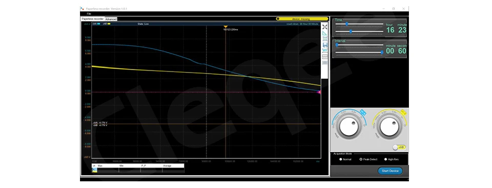
Common software interface
The Recorder software has an interface consistent with the oscilloscope software, so to be familiar to the user.
Equipment monitoring
After the software interface is opened, the OSC482 device status will be monitored in real time. When the hardware device is connected to the USB port of the PC, the software interface will display a blue background and a message.
If the hardware get disconnected or the software have no access to the device, then the display background will become yellow, showing a text alert.
We Recommend


New Arrivals
New products from manufacturers at wholesale prices


